Powering robot payloads from the robot battery: DC-DC conversion, distribution and protection
Updated 2026-11-04 · YUANZHI ROBOTICS engineering team
Power is the part of a payload that nobody looks at until something resets in the field. A sensor payload mixes a compute module that must never lose power with motors, heaters and radios that pull sharp peaks, all fed from a battery whose voltage swings by 20 percent between full and empty. This guide explains what the robot's payload port actually provides, when a payload needs its own battery, how we arrange the input stage, the DC-DC rails and the distribution board, how power-up is sequenced, and the handful of mistakes behind most brownouts and resets.
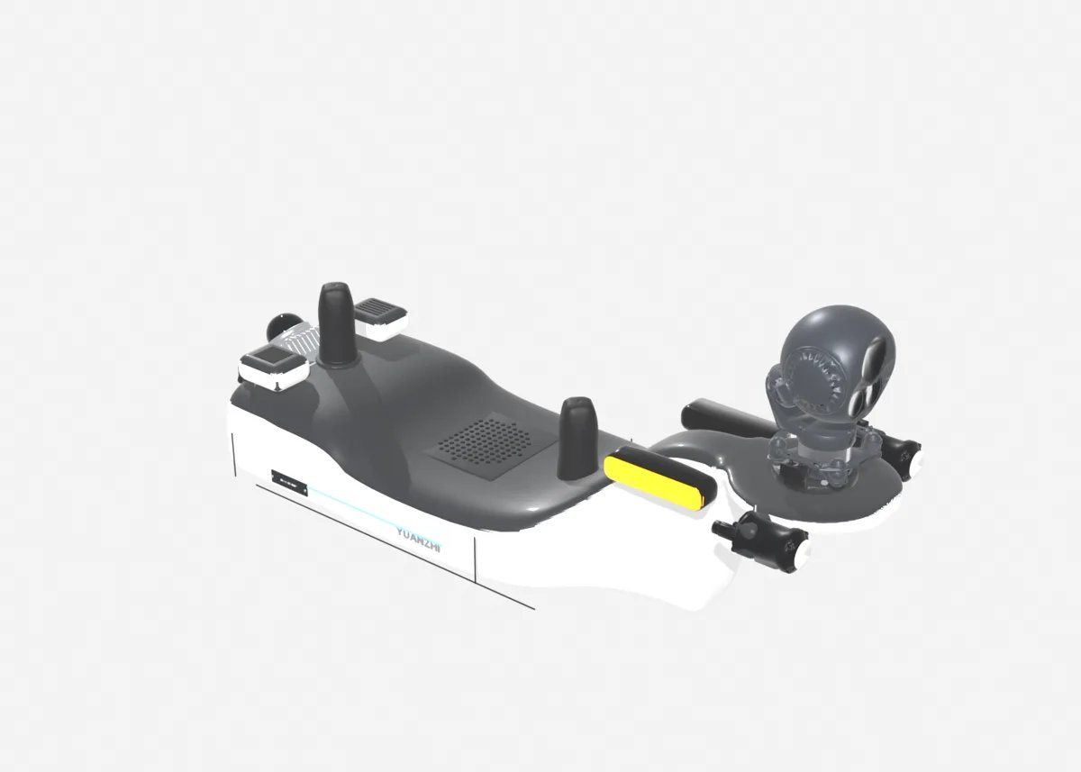
What the robot gives you
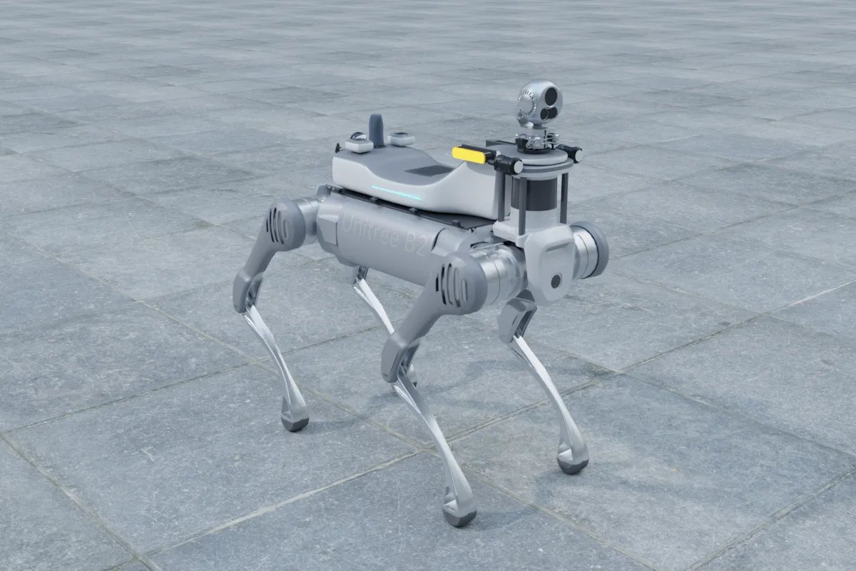
Every quadruped and UGV built for payloads exposes a power connector on its back. It carries the battery voltage, unregulated, through a fuse or an electronic switch with a current limit. On Go2, Lite3 and similar robots that is a nominal 24 V (about 21 to 29 V over the discharge range) at a few amps. On B2, X30 and the larger UGVs it is a nominal 48 to 58 V bus at a few amps more. The documentation gives a continuous rating; the real limit is usually the electronic switch's trip point under a short peak, which the manual rarely states. We measure it on each platform before relying on it.
The port is enough for a mapping payload: a Livox Mid-360 (about 7 W), a depth camera (2 to 4 W), a Jetson Orin NX module and carrier (15 to 25 W), a GNSS receiver and a Wi-Fi link, around 35 to 45 W in all. It is not enough for an inspection head with a PTZ dome (10 to 30 W with the heater), a 5G router (10 to 15 W), an acoustic imager, a pumped gas block and lighting: 60 to 120 W with peaks above that, which also takes a noticeable bite out of the robot's own runtime. Those payloads get their own battery.
Payload battery or not
A payload battery adds weight (a 48 V, 10 to 15 Ah lithium pack with its management board is 3 to 5 kg) but it decouples the payload from the robot. The payload runs on the bench, moves to another robot without touching the robot's wiring, keeps uploading and updating at the dock while the robot charges, and never trips the robot's payload port. We fit one on every inspection payload for B2 and X30 and on none of the mapping kits for small robots. The battery charges at the dock through the payload's own contacts or through the robot's charging bus where the manufacturer allows it, as described in our guide on docking and charging.
With a payload battery the robot's port is still used, but only for a trickle of state: the payload senses the robot's bus voltage to know that the robot is on and to detect the dock, and in some builds the robot's port tops up the payload battery during long rounds.
The input stage
Whatever the source, the payload has one input stage and nothing is connected to the raw bus directly. The stage has:
- a locking connector with the power pins rated for the current and a mating sequence that connects ground first;
- reverse-polarity protection, which on a 48 V bus is a P-channel MOSFET arrangement rather than a diode, to avoid the diode's heat;
- a transient suppressor and a small filter against the robot's own motor noise, which on a quadruped is considerable;
- an inrush limiter, so that plugging a payload with large input capacitance into a live port does not trip the robot's electronic switch;
- a master switch or an enable line from the robot, so the payload can be shut down without unplugging it;
- a voltage and current measurement that the compute module reads.
Rails and the distribution board
Downstream of the input stage, the distribution board creates one rail per voltage and gives each consumer its own fused, switchable output. A typical inspection payload has:
- a 12 V rail for the LiDAR, cameras, the PTZ head and the 5G router, from a 48-to-12 V converter sized with 50 percent margin over the sum of the loads, because converters run cooler and live longer well below their rating;
- a 5 V rail for small sensors, USB devices and the microcontroller that supervises the board;
- the compute module's own converter, fed from the input stage and not from the shared 12 V rail, with enough input capacitance to ride through a 10 ms sag;
- a separate converter or a direct battery feed for motors, heaters and pumps, so that their inrush and their ripple never reach the sensor rails;
- a 48 V pass-through for a PTZ dome that accepts it, which avoids one conversion stage entirely.
Each output is switched by a load switch or MOSFET under the supervisor's control, so the compute module can power-cycle a hung sensor without a hand on the robot, and each has a current measurement. A board of this kind is a single PCB of about 100 by 80 mm with the converters as modules on it, mounted on the inside of the shell with the converters' heat conducted to the shell wall.
Sequencing power-up
Everything on at once is what trips the robot's port and what leaves sensors in odd states. The supervisor microcontroller brings the compute module up first and waits for it to boot, then enables the LiDAR, the cameras and the radio one at a time at intervals of a second or two, then the PTZ head and finally any heater or pump. On shutdown the order is reversed, with the compute module last so that it closes its recordings cleanly. A hardware watchdog on the supervisor restarts the compute module if the application stops responding, which is the one piece of automatic recovery we always fit.
Cabling and connectors
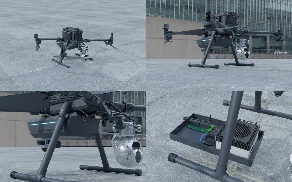
Power and data to each sensor run in a jacketed loom with locking connectors (M8 and M12 circulars for sensors, the robot manufacturer's own connector at the port, a sealed rectangular connector for the PTZ head). Power wires are sized for voltage drop, not only current: 2 A over a 1.5 m run of thin wire at 12 V loses enough to upset a LiDAR at the low end of the battery. Every cable is labelled at both ends, and the loom is clipped to the structure so that leg motion and vibration do not work the connectors loose.
Mistakes we see
- Sharing a rail between the compute module and a motor or heater: the classic cause of resets when the gimbal moves or the heater switches on.
- Converters sized to the nominal load: they run hot in a sealed shell and fail in summer.
- No inrush limiting: the payload works on the bench from a lab supply and trips the robot's port in the field.
- Grounding the payload to the robot at more than one point: a loop that puts motor noise into camera and LiDAR data.
- No current measurement: a failing sensor or a stuck heater is found only when the battery is flat.
- Running the whole payload from the robot's port to save weight, then losing a third of the robot's runtime and tripping the port on peaks.
If you are specifying a payload, ask the supplier for the power architecture as a one-page diagram: source, input stage, rails, what is on each, and how power-up is sequenced. If you are building one, start from the load table and the robot's measured port behaviour, and the rest follows. We are happy to look at either.
FAQ
What does the robot's payload port provide?
Battery voltage, unregulated, at a limited current: typically 24 V on Go2 and Lite3 class robots and 48 to 58 V on B2 and X30 class robots, with a few amps available. It is enough for a LiDAR, a depth camera and a Jetson module. A PTZ dome with a heater, a 5G router and an acoustic imager exceed it, and the port's protection will trip under their peaks.
When does the payload need its own battery?
When its average draw exceeds what the port supplies, when the customer wants the payload to run on a bench or on another robot, or when the robot's runtime matters more than the payload's weight. A 48 V, 10 to 15 Ah pack runs a 100 W inspection head for about five hours and charges at the dock alongside the robot.
Why does my Jetson reset when the gimbal moves?
Because the gimbal or the pan-tilt motors share a rail with the compute module and their inrush pulls the rail below the module's undervoltage threshold for a few milliseconds. Give the compute module its own DC-DC stage with input capacitance, and put motors and heaters on a separate rail with soft-start.
Do I need isolated DC-DC converters?
Not for most payloads: the robot and payload share a chassis ground and non-isolated converters are smaller and more efficient. Isolation is used where a sensor's manual requires it, for gas sensors with their own reference, and where the payload battery and the robot bus must never be connected together through a fault.
How do I measure what the payload is drawing?
Put a current sense on each rail of the distribution board (an INA226 class shunt monitor on I2C is the usual part) and log it on the compute module. The control centre shows the per-rail current, which is also how a failing sensor or a heater that stays on is found before it flattens the battery.