Mapping payload for robot dogs: LiDAR SLAM hardware setup from sensor to map
Updated 2026-11-04 · YUANZHI ROBOTICS engineering team
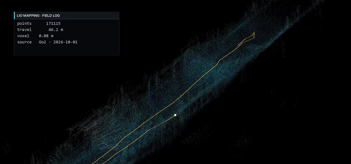
Building a map is the first thing every autonomous robot dog does at a new site, and the quality of that map decides how well it localizes and navigates afterwards. The software is well known: FAST-LIO2, LIO-SAM and their descendants are open source and run on a Jetson. What decides whether the map comes out clean is the hardware setup around them: which LiDAR and IMU, where they sit, how they share a clock, how the extrinsics are measured, and how the recording is turned into a final map. This guide covers that hardware side.
Sensors
- LiDAR: a Livox Mid-360 for most work. Its 360° horizontal and 59° vertical field of view covers walls, floor and ceiling from a mast on the robot's back, it has a built-in IMU, it weighs 265 g and draws about 7 W. For long outdoor ranges a 32-line spinning LiDAR sees further at a higher mass and power cost; our comparison guide covers the trade-off.
- IMU: the Mid-360's built-in IMU is enough for LiDAR-inertial odometry on a walking robot. An external IMU (a tactical-grade MEMS unit) is added when runs are long and featureless or when the accuracy requirement is tight.
- Depth camera: an Intel RealSense D435i or D455 at the front, looking forward and down. It is not part of SLAM; it fills the LiDAR's blind cone close to the robot for obstacle detection and stairs, and gives colour for the map.
- GNSS: a dual-antenna RTK receiver when mapping outdoors over hundreds of metres, to anchor the map to real coordinates and bound drift.
Placement
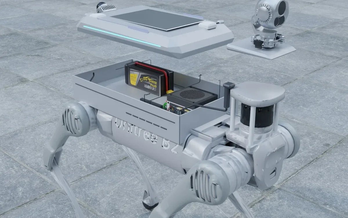
The LiDAR goes on a short mast at the rear of the back plate, high enough that its lower rays clear the robot's body and the payload shell, which on a Go2 class robot means about 10 to 15 cm above the plate. Rear placement keeps the forward view clear and lets the LiDAR see the floor behind and beside the robot. The mast is stiff, not tall: every millimetre of flex is noise in the point cloud. The depth camera sits at the front edge of the shell, pitched down 10 to 20°. The compute module and any external IMU sit inside the shell, the IMU rigidly bolted to the same plate as the LiDAR mast with no isolator between them. Antennas go on the rear corners outside the LiDAR's field of view.
Vibration isolation is a trade-off. The whole payload sits on isolators between the adapter plate and the robot's back, which protects the sensors from the footfall shock. The LiDAR and IMU are never isolated from each other, because the SLAM stack needs them to move as one body.
Time synchronization
A LiDAR-inertial stack is only as good as the timestamps. With the Mid-360's internal IMU, both streams share the LiDAR's clock and nothing more is needed; the Jetson's clock is used only for recording. With an external IMU, the IMU and LiDAR must be on one time base: the Mid-360 accepts PTP, so the Jetson runs a PTP master and the IMU is timestamped on arrival with a hardware trigger or on a microcontroller synchronized to the same master. A camera that will be fused later is triggered by the LiDAR's PPS or timestamped the same way. We check synchronization on every payload by recording a sharp rotation and confirming that the IMU and LiDAR see it at the same instant to within a millisecond.
Calibration
The extrinsic between the LiDAR and the IMU comes from the CAD when the IMU is the LiDAR's own, and is refined with an open-source LiDAR-IMU calibration on a recorded figure-of-eight run when it is external. The LiDAR-to-camera extrinsic is measured with a target board. The LiDAR-to-robot-body transform, which the navigation stack needs, is measured against the robot's own odometry. Calibration is repeated after any mechanical change to the mast and checked before each site deployment by looking at a flat wall in the map: a double surface means the extrinsic or the synchronization has drifted.
Compute
A Jetson Orin NX 16 GB on an industrial carrier runs the LiDAR driver, FAST-LIO2 or LIO-SAM at 10 Hz, the depth camera, the navigation stack and recording, with headroom left. A light stack alone (LiDAR driver and odometry at reduced map resolution) runs on the robot's own computer on Go2 EDU and Lite3, which is how trials often start. The recording goes to an NVMe drive in the payload; a mapping run of an hour at 10 Hz is tens of gigabytes of point clouds and IMU data. The Jetson is bolted through a thermal pad to the aluminium shell so that it holds its clock speed in a sealed enclosure; our guide on onboard compute covers the alternatives.
From recording to map
The real-time stack gives the operator a live map and a position during the run, which is what the operator needs to see that the site is covered. The final map is not that live map. After the run, the recording is rebuilt offline on the payload computer or on a workstation: loop closure and global optimization remove the accumulated drift, dynamic objects (people, vehicles, doors that were open) are filtered out, the floor is identified, and the result is exported as the point cloud map for localization, a 2D occupancy grid for path planning and a mesh for the operator's view. On our payloads this rebuild runs automatically when the operator stops the recording, so that the robot is ready to localize and navigate against the clean map a few minutes after the mapping walk, without a laptop.
Before the first mapping run
- Confirm time synchronization with a sharp rotation and check the IMU and LiDAR timestamps agree.
- Look at a flat wall in the live map from two positions; a double surface means the calibration is off.
- Check the recording drive has space and that recording survives a power cycle.
- Walk a loop that returns to the start and confirm the start point lines up; that is the loop-closure check.
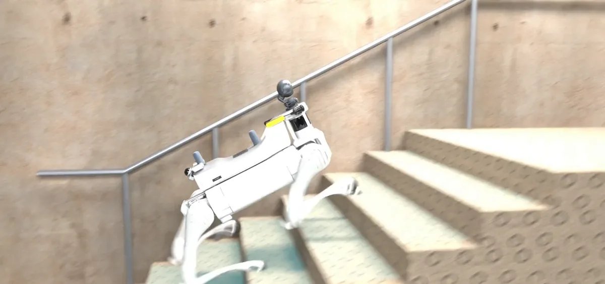
- Walk slowly through doorways and on stairs the first time; a quadruped's pitch on stairs is where odometry is most stressed.
- Keep the LiDAR window clean and check the mast bolts; both are found loose more often than any software fault.
What the payload weighs and draws
The complete mapping payload (LiDAR, depth camera, Jetson, GNSS, Wi-Fi, structure and cables) is 1.5 to 2.5 kg and draws 35 to 45 W, which runs from the robot's payload port on Go2, Lite3, AS2, B2 and X30 alike. It is the same payload family across those platforms, so a map built on one robot localizes another.
If you are planning a mapping payload for a quadruped, tell us the robot, the site (indoor, outdoor or both) and the accuracy you need; we will tell you which LiDAR and IMU we would fit and what the mapping and rebuild workflow looks like for that site.
FAQ
Which LiDAR is right for a mapping payload on a quadruped?
A Livox Mid-360 for most indoor and near-outdoor work: 360° horizontal field of view, 59° vertical, 40 m range at 10 percent reflectivity, 265 g, about 7 W, and a built-in IMU. For long outdoor ranges a 32-line spinning LiDAR (Ouster OS1, RoboSense Helios) sees further at 2 to 3 times the mass and power. Our LiDAR comparison guide covers the alternatives.
Does the LiDAR need an external IMU?
The Mid-360's built-in IMU is sufficient for FAST-LIO2 class odometry on a walking robot. An external tactical-grade IMU improves robustness on long featureless corridors and during fast turns, and is what we fit when the customer's accuracy requirement is tight.
Can the robot's own computer run the SLAM stack?
On Go2 EDU and Lite3 a light stack (LiDAR driver and FAST-LIO2 at reduced map resolution) runs on the robot's computer. Anything that also records, runs a camera or navigates gets a Jetson Orin NX in the payload, which also keeps the robot's controller untouched.
Why rebuild the map offline?
Real-time odometry drifts over a long run and has no loop closure or dynamic-object removal. Rebuilding from the recorded point clouds and IMU data with loop closure, global optimization and removal of people and vehicles that walked through gives a clean map that the robot then localizes against on every later round.
What accuracy does a quadruped mapping payload achieve?
Indoors, with loop closure, a few centimetres of consistency across a building floor. Outdoors over hundreds of metres, decimetre-level drift without GNSS and centimetre-level with RTK GNSS fused in. The walking motion itself is not the limit; the IMU-LiDAR synchronization and extrinsic calibration are.