Automatic gauge and meter reading on a robot dog: cameras, software and accuracy factors
Updated 2026-11-07 · YUANZHI ROBOTICS engineering team
Reading gauges is one of the most common reasons to put a robot dog into a plant room, substation or pump station. The robot walks a fixed route, stops at known points, points a camera at each instrument and turns the image into a value, a state or an alarm. This guide explains what that takes in practice: which camera, how inspection points are made repeatable, how the reading software works for different instrument types, what limits accuracy, and how to validate results on your own site instead of trusting a number from a brochure.
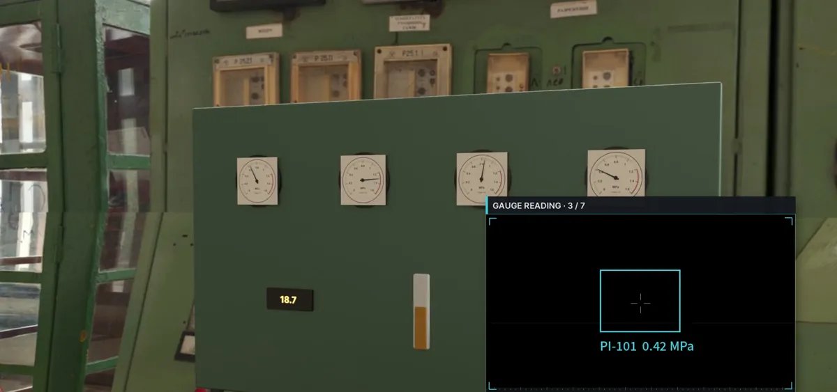
What a robot dog can read
| Instrument type | Output | Main method |
|---|---|---|
| Analogue dial gauges (pressure, temperature, level) | Numeric value with unit | Dial detection, perspective correction, needle angle mapped to the scale |
| Digital displays (seven-segment, LCD panels) | Numeric value or text | Display detection, rectification, OCR trained on segment fonts |
| Indicator lamps | On, off, colour, blinking | Lamp localisation, colour and brightness over several frames |
| Switch and breaker positions, valve handles | Discrete state | Classification of the handle or lever position against reference images |
| Oil level windows, flow indicators | Level or presence | Region measurement against marked limits |
Most sites mix all of these on one route, so the software has to handle each point with its own reading method and its own validity checks.
Choosing the camera
The camera decides more about reading quality than the algorithm does. Three things matter.
- Zoom. A robot dog cannot always walk up to an instrument: gauges sit behind railings, above pipework or across a cable trench. Optical zoom lets the robot stay on its safe path and still fill the frame with the dial. Digital zoom only crops pixels and does not add detail. As an example of a gimbal camera used on payloads, SIYI lists the ZR30 with a 1/2.7-inch Sony sensor, 8 MP, 30x optical and up to 180x hybrid zoom, three-axis stabilisation and Ethernet and HDMI output. Its own FAQ notes that zoom is not available when recording is set to 4K, the kind of detail that matters when configuring a reading pipeline.
- Resolution where it counts. What matters is how many pixels land on the dial and its scale marks, not the headline megapixels. A small gauge at a distance needs zoom; a large panel close up does not. Plan each point so the instrument fills a good part of the frame.
- Lighting. Plant rooms are often dim and unevenly lit, and glass faces reflect ceiling lights and the robot's own lamp. A fill light helps in the dark, but it should be placed so its reflection does not land on the dial. Exposure should be set from the instrument region, not the whole frame.
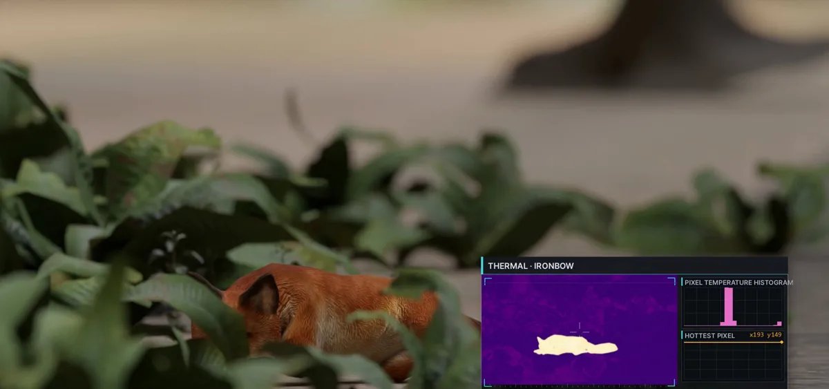
Thermal cameras are a separate task: they show temperature distribution on equipment, but do not replace a visible camera for reading dials and displays. Many inspection payloads carry both on the same gimbal.
Repeatable inspection points and gimbal presets
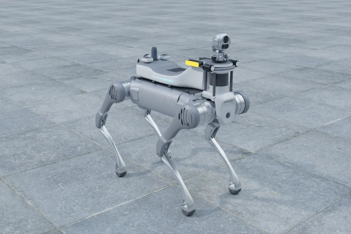
Reliable reading starts with the robot arriving in the same place every time. The route is taught once on a LiDAR map: the robot is driven to each point, its position and heading are saved, and for each instrument the gimbal pan, tilt and zoom are stored as a preset together with a reference image.
- On each round the robot localises on the saved map, walks to the point, stands still and lets the body settle before capturing.
- The gimbal moves to the preset, then a fine alignment step compares the live image with the reference and corrects small pan and tilt offsets, so slight differences in standing position do not move the instrument out of frame.
- Several frames are captured per point. Readings that disagree between frames are flagged rather than averaged blindly.
Localisation quality therefore feeds straight into reading quality. A map built with a rigid, back-mounted LiDAR and a stable localisation stack makes presets far more dependable than a robot that stops in a slightly different place each day.
The reading pipeline
- Detection. A detector locates the instrument in the image and confirms it is the expected one for this point. If the expected instrument is not found, the point is reported as not read, not as a value.
- Perspective correction. The robot rarely views a dial head-on. The dial ellipse or the display corners are used to rectify the image into a front view, so angles and characters are measured in the instrument's own plane.
- Needle and scale reading. For dials, the software finds the needle line and the scale arc. The needle angle is converted to a value using the scale start and end angles and the range recorded for that gauge when the point is taught. Non-linear scales need their calibration points entered explicitly.
- OCR for digital displays. Seven-segment and LCD displays need OCR trained on those fonts; general text OCR often confuses segments. Decimal points, minus signs and units are checked against the expected format.
- State classification. Lamps, switches and valve handles are classified against reference examples, using several frames for blinking lamps.
- Validity checks. Each result carries a confidence value and passes plausibility checks: within the instrument range, consistent across frames, no implausible jump since the last round.
All of this runs on the payload computer on the robot, for example a Jetson Orin NX 16 GB, so the robot does not depend on a continuous video link to produce readings.
What affects accuracy
| Factor | Effect | What helps |
|---|---|---|
| Viewing angle | Strong obliquity compresses the scale and can hide the needle behind the bezel | Choose points closer to head-on, correct perspective, avoid extreme angles |
| Glare and reflections | Bright spots hide the needle or segments | Shift the point or tilt slightly, polarising filter, careful fill light |
| Distance and zoom | Too few pixels on the scale marks limits resolution | Optical zoom so the dial fills the frame |
| Vibration | Motion blur from the robot or from vibrating pipework | Settle time before capture, short exposure, gimbal stabilisation, multiple frames |
| Scale resolution of the instrument | A coarse scale cannot be read more finely than its marks allow | Set expectations per gauge from its own graduations |
| Dirt, condensation, damaged glass | Low contrast, false needle lines | Confidence threshold, flag for maintenance instead of guessing |
What accuracy to expect and how to validate it
There is no single accuracy figure that holds across sites, because it depends on the instruments, their placement and the light. We do not quote a percentage before seeing the site. A sound way to establish it is:
- Pick a representative set of points, including the difficult ones.
- Run several rounds at different times of day and record the robot's readings next to manual readings taken at the same moment.
- Compare the difference with each gauge's own scale division, and count how often a point is reported as not read.
- Adjust points, presets and lighting where errors cluster, then repeat.
A result that says "not read, low confidence" is more useful than a confident wrong value, so the rate of rejected readings belongs in the acceptance criteria rather than being hidden.
Alarms, reports and integration
- Each point has its own thresholds: high, low, wrong state, or change since the last round. Breaches raise an alarm with the image attached so an operator can confirm it in seconds.
- After each round a report lists every point with value, image, confidence and status, and trends are kept per instrument.
- Results can be passed to existing systems over common interfaces such as MQTT, HTTP or Modbus, or exported as files, depending on what the site already runs.
- Images are stored with every reading, so any value can be audited later.
Our complete inspection kit, from US$8,690, includes the cameras, payload computer, mapping and the inspection application with gauge reading; the entry mapping kit starts from US$2,000 for projects that need the map first. To get a realistic view of what can be read on your site, send us the robot model, the instruments and task, a description or photos of the site, and the delivery country.
FAQ
Can a robot dog read analogue gauges without changing the instruments?
Yes. Standard dial gauges, digital displays, indicator lamps and switch positions can be read from camera images without modifying the instruments, provided each one is visible from a point the robot can reach safely and the light allows a clear image.
Why is optical zoom important?
The robot often cannot walk close to an instrument because of railings, pipework or trenches. Optical zoom puts more real pixels on the dial and its scale marks from a distance; digital zoom only crops the image and adds no detail.
How accurate is automatic gauge reading?
It depends on viewing angle, glare, distance, vibration and the gauge's own scale divisions, so we do not quote a general percentage. Accuracy is established on site by comparing robot readings with manual readings over several rounds.
What happens if a gauge cannot be read?
The point is reported as not read with a low-confidence flag and the image attached, rather than producing a guessed value. Rejected readings are tracked as part of acceptance and usually point to a placement, glare or lighting fix.
Can readings go into our existing alarm or SCADA system?
Usually yes. Readings, states and alarms can be sent over common interfaces such as MQTT, HTTP or Modbus, or exported as reports, with the captured image stored for each reading.