Livox Mid-360 vs the built-in Unitree L1 LiDAR for mapping on a robot dog
Updated 2026-11-06 · YUANZHI ROBOTICS engineering team
Every Unitree Go2 ships with a LiDAR in its head, so the first question on a mapping or inspection project is whether a second LiDAR is needed at all. The short answer is that the built-in Unitree L1 was designed for obstacle avoidance and the Livox Mid-360 for mapping and localization, and most serious projects end up running both. This guide compares the two on the numbers that matter for SLAM on a walking robot, explains where each one fails, and gives a decision table by type of project.
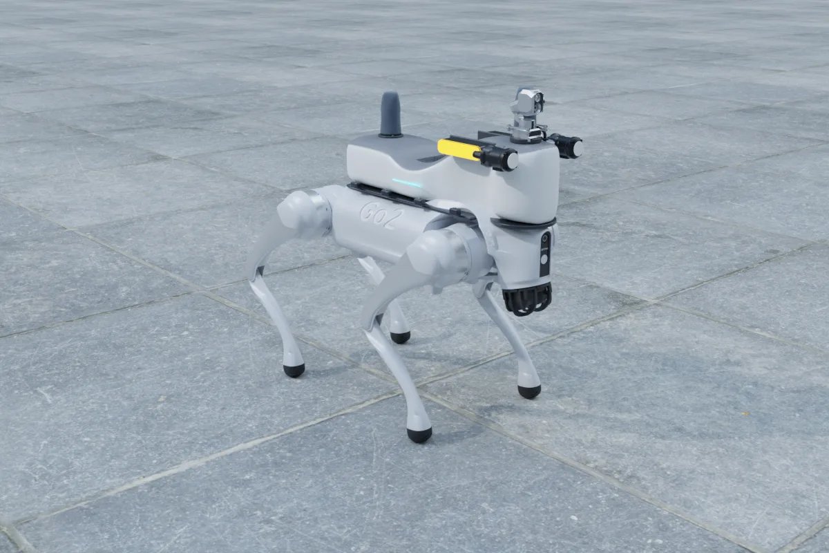
The two sensors side by side
| Unitree L1 (in the Go2 head) | Livox Mid-360 (on the back) | |
|---|---|---|
| Design purpose | Obstacle avoidance, terrain right in front of the robot | Mapping, localization, navigation |
| Point rate | About 21,600 effective points per second | About 200,000 points per second |
| Range | About 30 m on bright targets, minimum 5 cm | 40 m at 10 percent reflectivity, 70 m at 80 percent, minimum 0.1 m |
| Field of view | 360 by 90 degrees, hemispherical, sees the ground close to the robot | 360 by 59 degrees (minus 7 to plus 52), little ground right at the feet |
| IMU | Built in | Built in, used by LiDAR-inertial SLAM |
| Mounting | In the head, moves with every step | Rigid bracket on the back rail |
| Weight and power | Part of the robot | 265 g, about 6.5 W, 9 to 27 V, Ethernet |
Figures are from the manufacturers' public datasheets; real performance depends on surfaces, mounting and software.
Why the L1 alone struggles with maps
- Sparse points. With roughly a tenth of the Mid-360's point rate, each scan carries little structure. In long corridors, car parks and open plant halls the scan matcher has too few features to hold its position, and the map stretches or bends.
- Head motion. The head pitches and rolls with the gait. The robot's state estimate compensates partly, but every error in that compensation lands in the map.
- Range. Large rooms and outdoor areas put walls and structures beyond what the L1 reliably returns on dark or angled surfaces.
For a demonstration in an office or a small lab, these limits are acceptable and the L1 builds a usable map. They become a problem as soon as the map must be repeatable across days, the area grows past a few hundred square metres, or inspection points must be revisited within a few centimetres.
What the Mid-360 changes
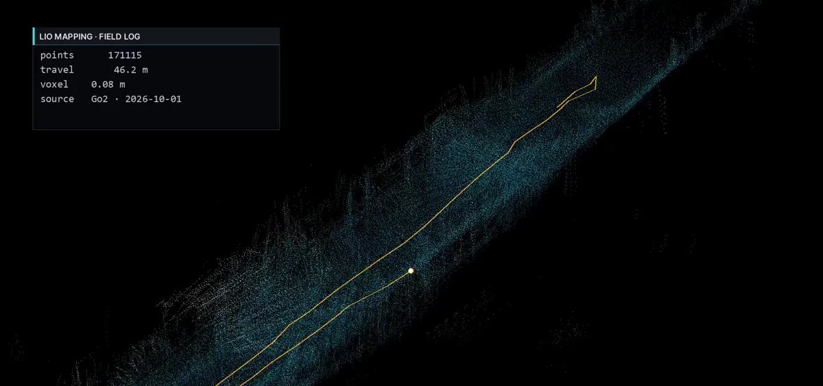
Mounted rigidly on the back, the Mid-360 gives dense scans with its own IMU in the same housing, which is exactly what LiDAR-inertial odometry such as FAST-LIO2 or Point-LIO expects. In our builds the difference shows up as straight corridors staying straight, loops closing without manual help, and localization on a saved map that stays stable through doors and turns. Its range also makes outdoor yards, substations and car parks practical.
Why we usually keep both
The Mid-360's field of view starts at minus 7 degrees, so the floor directly in front of and around the robot is in its blind cone. The L1 sees that area well. The practical split is: Mid-360 for mapping, localization and medium-range obstacles; L1 for steps, kerbs and low obstacles right at the feet. Both feed the navigation costmap.
Mounting and integration notes
- Use a machined aluminium bracket with a measured offset to the body frame; vibration from a flexible mount is visible in every map.
- Keep the sensor's upper field clear of antennas and the gimbal, or mask those angles in software.
- Power it from a regulated rail on the payload board, not directly from the robot battery, and give it its own Ethernet port or a small switch shared with the computer.
- Synchronise time between the Mid-360, the payload computer and the robot state, or the IMU fusion degrades.
- Build the final map offline with loop closure and dynamic object removal rather than exporting the live map.
Decision table
| Project | Recommendation |
|---|---|
| Demo, teaching, small lab | L1 only is acceptable |
| Indoor inspection rounds, repeated daily | Add Mid-360, keep L1 for close obstacles |
| Site or building map as a deliverable | Mid-360 with offline rebuild |
| Outdoor yards, substations, car parks | Mid-360; consider RTK for outdoor absolute position |
| SLAM research | Mid-360, record raw data from both sensors |
Our entry mapping kit for the Go2 adds the Mid-360 with a machined bracket, regulated power and cabling, and a ROS 2 mapping setup; the full inspection kit adds cameras, computing and the inspection application. If you tell us the robot, the site size and what the map is for, we will tell you whether the built-in sensor is enough before you buy anything.
FAQ
Can I build a map with only the Go2's built-in L1 LiDAR?
Yes, for small indoor areas and demonstrations. The point cloud is sparse, the sensor sits in the head and moves with the gait, and long corridors or open halls give it little to lock onto, so maps drift and localization is less repeatable than with a back-mounted Mid-360.
What does the Mid-360 add in numbers?
From the manufacturers' datasheets: about 200,000 points per second against roughly 21,600 effective points per second for the L1; up to 40 m range at 10 percent reflectivity against about 30 m for bright targets on the L1; a 360 by 59 degree field of view with a built-in IMU; 265 g and about 6.5 W.
Do I lose anything by adding the Mid-360?
Weight and power (around 0.5 kg with mount and cable), a blind cone directly around and below the sensor, and one more device on the Ethernet and power rails. Its lower field of view starts at minus 7 degrees, so it does not see the floor right at the robot's feet: that is what the L1 is good at.
Which SLAM works best with the Mid-360 on a quadruped?
LiDAR-inertial odometry such as FAST-LIO2 or Point-LIO using the Mid-360's own IMU, with an offline pass for loop closure and removal of moving objects to produce the final map. Pure scan matching without the IMU struggles with the vibration of walking.
Where should the Mid-360 be mounted?
On the back rail, as high and as far forward as the payload allows, tilted slightly forward if the work is mostly indoors, on a rigid aluminium bracket with a known offset to the robot body. A wobbly or 3D-printed bracket shows up directly as map noise.